Monday, 25 August 2008

The Decking


Now the balustrades are in position it will be important to have some decking down before we attempt to attach the clinker cladding. Alastair's father, Tim Fison, kindly sanded down the top of the 5 beams and noggins. He painted the tops of the noggins whilst Alastair took the time to give the tops of the beams a coat of bitumen paint. The decking battens have been sanded and a coat of warm linseed oil applied.


The geometry of the bridge is complicated as the bridge is offset. This means that the design is basically a rectangular shape with a triangle added at each end/ It is these triangular parts of the puzzle which give us the most headaches when it comes to wanting to lay a flat, even deck. The two sidebeams are level and in the same plane at the centre. As the decking is going to follow the offset angle from one end of the bridge to the other we are not going to be able to maintain an even, horrizontal surface at the start on each end.
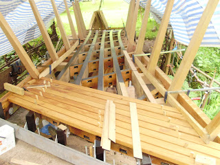


The sixth beam has always been lower than the other beams at the higher end of the bridge. This has meant that a strip of oak batten has to be added for 5m.


I have decided to have the decking come short of the interior cladding which will allow run-off to fall straight down through the bridge framework to the ground and stream below. It also means that there will be a gap between the two sets of clinker cladding, so allowing run-off to escape easily. But, the decking will be laid, full length, between the two outside beams at both ends. The decking is attached to each of the five beams with 2 countersunk and plugged stainless steel screws.

Installation of Balustrades


Each of the balustrades were cut to fit between the outer and inner beam, on site. The two beam faces had already been made as near vertical as possible when we cut and fitted the noggins. All we had to do was scribe the inner-beam face onto the toe of each noggin and cut off the surplus. Not as easy as it sounds as it always take two or more attempts to get it right.


The balustrades were each set with a lean towards the end of the bridge - at multiples of 5 degrees. So the middle balustrade was anchored at 90 degrees with the furthermost balustrade ending up at 125 degrees.


The heel and toe of the balustrade was then painted with bitumen by Alastair, as done on the noggins to minimise water penetration.


The balustrades were secured with stainless steel threaded rod from the outside beam through the foot of the balustrade and out through the other side of the inner beam. We also used stainless steel coach bolts to secure through the outer beam and into the leg of the balustrade. This gives a very strong hold.

The excellent team was ably assisted and inspired by Alastair & Tim Fison and Robin Le Mare.

Preparation of Balustrades


The balustrades were cut to size using templates over two years ago, so adjustments had to be made as the geometry of the bridge has changed somewhat. This cutting out new heel and toe sections where necessary and gluing them onto the main leg of the balustrade using two-part marine epoxy glue.
The timber used was straight grained, quality, air-dried oak for the 22 uprights.

Preparation of Balustrade Uprights


Over two years ago the uprights were cut out using templates made to from scale drawings. As the geometry of the bridge has since changed we had to revisit the timbers and make adjustments. This included cutting out toe sections which were to be glued to the foot of the uprights. All the timber used was air-dried.

Saturday, 14 June 2008

Securing Noggins to Beams


We changed our method of securing the noggins to the beams as we realised that it was impossible to take the bridge apart and drill through each beam and noggin, secure them with threaded stainless steel bar, and hope that the bridge would be level at the end of play. Instead we cut notches in the sides of the noggins which took 6 inch (80mm) stainless steel coach bolts. These bolts were used to mark a position on the inside of the beam, a pilot hole was then drilled. The noggin was replaced and the coach bolts driven home.

The pictures below show the architect, William McMorran, and Tim Fison securing the noggins to the beam structure over the weekend of the 11th may 2008.


Scribing Lines for Placement of Balustrades and Noggins


Once the beams were made level and secure to the foundations at either end we had go about scribing lines across the top sides of the beams. These lines would assist in positioning the noggins and the balustrades. The engineer's drawings didn't seem to work out so we divided the length of the outside beams by the number of balustrades. From these points we were able to scribe across the tops of the beams, using a chalk line and a scratching awl.

The noggins were then measured to fit into their designated positions by placing the noggin blank across the two beams and scribing the face of each beam onto the end of the noggin. They were then cut and adjusted until they fit their slot.

Balancing the Beams


Jonathan Wiltshire and I spent many days making the beams line and level - before we secured the beams to the end-plates.

New End-Plate Secured In Place

Stephen Mather and Stuart Graham secured the new end-plate in place on the 8th February 2008.

New End-Plate

A new end-plate was designed by Price & Myers and manufactured in Pershore, Worcestershire, by Steven Cooper. This was collected by me on 17th December 2007.